


Discover the Most Suitable DAS Solution for Your Needs
Schedule a free 30-minute call with one of our signal experts.


Everything you need to know about the technology, cost-effectiveness, and implementation
Prefer conversation rather than reading? Get in touch with an expert who can guide you to the right solution for your building.

Whether it's a crowd on a stadium, passengers in the airport, or employees in the enterprise office - Don't get the cell phone signal complaints anymore.
In-Building Distributed Antenna Systems (DAS) have become a critical part of both carrier cellular networks and enterprise infrastructure. But as the technology has evolved over the last 20 years it has become increasingly complex. The list of acronyms alone can be overwhelming: iDAS, oDAS, eDAS, active DAS, passive DAS, hybrid DAS, off-air DAS, and numerous others. This guide will describe common types of distributed antenna systems and effective implementation strategies.
This guide focuses on cellular DAS. For information about Public Safety DAS and ERRCS, see our other guide: Meeting NFPA and IFC Building Codes with an Emergency Responder Radio Coverage System (ERRCS).
Looking to deploy a DAS? Our nationwide team can design and install a 4G LTE or 5G DAS for Verizon, AT&T, or T-Mobile at your venue. Simply reach out to our team for more information.
A DAS is a network of antennas that sends and receives cellular signals on a carrier’s licensed frequencies, thereby improving voice and data connectivity for end-users.
In its most simplified form, a DAS has two basic components:
1 - A signal source
A Distributed Antenna System, as the name implies, “distributes” signal. But it generally doesn’t generate the cellular signal itself. A DAS needs to be fed signal from somewhere. Whether it's 4G LTE or 5G, there are four typical signal sources: off-air (via an antenna on the roof), an on-site BTS (Base Transceiver Station), and finally the newest approach: small cells.
2 - Distribution system
Once received, the cellular signal must be distributed throughout the building. There are four main types of distribution systems: active (using fiber optic or ethernet cable), passive, hybrid, and digital.
A distributed antenna system’s performance depends on the type of technology it uses. To understand what we mean by “performance,” we first need to understand the two main performance metrics: coverage and capacity.

To be able to compare the different technologies, we first need to review the two main performance reasons that DAS solutions are deployed: to provide coverage and capacity.
Some locations experience significantly more cellular data usage than others. Think of a sports stadium hosting the Super Bowl, or a large music venue hosting Justin Timberlake. If the venue relied on a nearby cell tower to provide coverage to all those users, the tower and the local network would quickly become overwhelmed and unstable. In such applications, a DAS with high capacity is the primary need.
If there's simply not enough usable signal reaching users, either because the cell tower is too far away or due to building materials such as low-E windows in LEED Buildings blocking cell signal, the primary need is coverage. For example, a newly-built LEED-certified hospital with concrete walls might have no indoor coverage and require a DAS. Highrises often use DAS deployments because the radio frequency noise levels at higher altitudes make the signal unusable.
Identifying one of these needs as the primary requirement of your project is an important first step. Choosing the right DAS technology means making trade-offs between coverage, capacity, and price.
The signal sources for a DAS system are one of the single most important factors in determining both the coverage area and capacity. No matter how well the distribution system performs, a DAS is always limited by the performance of the signal supplying the network. The signal source also determines what kind of signal the DAS distributes. For example, a 5G signal source is a requirement for a 5G DAS. The three main signal sources are off-air, BTS/NodeB/eNodeB, and small cell.
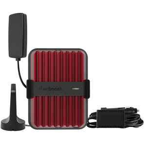
A DAS that uses an off-air signal (sometimes called a repeater) utilizes a donor antenna on the roof to receive and transmit signals from a cell carrier. Off-air signals are the most common signal sources for a DAS. If the signal at the donor antenna is very weak or the nearest tower is quite congested, using an off-air signal isn't typically feasible. But if the donor signal is strong and clear, then an off-air signal is often the easiest and most cost-effective signal source.
A DAS that uses an off-air signal source does not add any extra capacity to the carrier’s network and is primarily used to extend coverage at the edges of the network. These deployments are often the lowest cost option and are most suitable when the primary reason for deploying a DAS is to extend coverage inside a building.
Almost all DAS systems are can use off-air signal, but Wilson Electronics, SureCall, and Cel-Fi are most often associated with this type of deployment. Off-air DAS deployments have seen a resurgence with the roll-out of 5G, particularly on mmWave bands.

Choosing an integrator with a strong RF (radio frequency) experience is critical when implementing an off-air DAS system. The performance of the DAS will depend strongly on proper evaluation and optimization of the donor signal.
Base Transceiver Station (BTS), NodeB, eNodeB, gNodeB refer to the technology used inside cell phone towers to generate a cellular signal. For simplicity, these technologies are often referred to simply as a BTS signal source.
The connection between a cell carrier's BTS and the core network typically requires a dedicated fiber connection that is usually installed by the carrier themselves. A distributed antenna system in a large stadium or airport may even connect to multiple BTSes—one for each carrier—to handle the load of tens of thousands of users calling, texting, and using data simultaneously.
DAS systems that use BTS signal sources typically take longer to deploy and are more expensive; each carrier must run their own fiber and the BTSes themselves are typically at least $50k+ each.
Nokia and Ericsson are the two most common vendors of BTS and eNodeBs for DAS deployments.

Small cells are the latest technology used by carriers to provide cellular service inside buildings. There are several variations of small cells, including femtocells, picocells, nanocells, and metrocells. These are all basically the same technology—they create a secure tunnel back to the carrier’s network over a normal Internet connection and generate a high-quality wireless signal.
The typical coverage area of a small cell is only about 5,000 to 15,000 square feet, and they are relatively expensive. While covering larger venues with dozens of small cells isn’t cost-effective, the coverage area of a small cell can be greatly expanded by using them as a signal source for a distributed antenna system. One limitation of small cell technology is that they require a reliable backhaul Internet connection to connect. Each enterprise-grade small cell typically supports around 200 users. We’ve installed many DAS deployments using small cells as a signal source, and the results are typically excellent. We expect this will be the fastest-growing new technology in the DAS space.
Nokia, Samsung, Casa Networks, Spidercloud, and Airspan are the most popular vendors of enterprise-grade small cells.

Depending on the setup of the DAS, it’s possible to mix and match the different signal sources listed above in a single venue. For example, one might use a small cell signal source for one carrier and bring the remainder of the carriers from an off-air donor antenna.
Whichever signal source a system uses, a DAS needs to amplify, distribute and rebroadcast it through the building. There are four main types of signal distribution technology: active, passive, hybrid and digital.
A passive DAS uses passive RF components such as coaxial cable, splitters, taps, and couplers to distribute signal inside a building. The farther the antenna is from the signal source and any amplifiers, the more attenuation (loss) there will be in the power broadcast from that antenna. Designing a passive DAS correctly requires calculating precise link budgets to make sure the outputted power at each antenna is equal.
Wilson Electronics and SureCall are the two vendors most commonly associated with passive DAS systems, but passive DAS equipment is also offered by more traditional vendors such as Commscope, SOLiD, and ADRF.

Passive DAS deployments are typically simpler than other types of distributed antenna systems, which our customers appreciate. However, performance limitations often mean that we recommend active or hybrid DAS systems for medium-sized and larger buildings.
An Active DAS converts the radio frequency transmissions from the signal source signal so they can be distributed via an optical or ethernet cable. A "master unit" combines the signals from multiple carriers and performs this conversion. Some Active DAS systems also "digitize" this signal which adds cost but improves performance (see below). Once converted, an Active DAS transmits the digital signal over fiber optic ("Fiber DAS") or ethernet cables to remote radio units (RRUs) that convert the signal back to an RF signal. These RRUs are also sometimes called "nodes" or even "active antennas" depending on the vendor and the architecture of the system.
Unlike their Passive DAS counterparts, Active DAS deployments minimize the use of coaxial cable used to distribute signal. In some cases there is no coaxial at all; this is called a "fiber to the antenna" or "fiber to the node" system.
Corning, Commscope, SOLiD, Comba Telecom, and ADRF all offer variants of active and fiber DAS systems.

A hybrid DAS combines the characteristics of passive and active systems. The RRUs are separate from the antennas, allowing the system to use both fiber optic cable and coaxial cable to distribute signal throughout a building. Because this configuration requires fewer RRUs, a hybrid DAS normally costs less than an active DAS.
A typical hybrid DAS configuration includes an RRU on each floor that converts from the digital signal to analog RF. The analog RF signal is then connected to multiple antennas on that floor with coaxial cable.
The same active DAS vendors (Corning, Commscope, SOLiD, Comba Telecom, and ADRF) all offer hybrid DAS options, typically at a lower cost than their "fiber to the antenna/node" solutions.
Cel-Fi also markets their QUATRA product line as a hybrid system due to its cost savings, even though the system is more similar to an Active DAS in some ways.

A Digital DAS converts each carrier's signal to zeros and ones before combining them and transmitting over fiber optic or ethernet cable. This conversion and combination process is computationally expensive, which makes digital DAS systems considerably more expensive than their analog counterparts.
One of the biggest benefits of deploying a Digital DAS is that they are much less susceptible to interference, and thus more performant. A second benefit is that Digital DAS platforms allow the capacity of the signal sources to be directed to different areas of a venue. This is particularly important when the capacity of a building shifts dynamically – think for example of a large cafeteria or event space on a school, university, or office space.
If both the signal source and Digital DAS platform support the "Common Public Radio Interface" (CPRI) specification, it's possible for a signal source's Baseband Unit (BBU) to communicate directly with the DAS master unit and through to the remote units without any conversion to an analog RF signal.
Corning, Commscope, ADRF, and SOLiD all offer Digital DAS platforms.
With three different signal sources and four different distribution systems, there are a total of twelve possible DAS configurations. In practice, however, there are far fewer. Here is an overview of the most common configurations, and the applications for which they are best suited.
This type of DAS costs less than other types and offers the shortest deployment time. This is particularly true when coverage for multiple carriers is necessary.
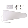
Donor antenna(s) aimed at towers
DAS Headend
Coaxial cables, taps, splitters
Indoor antennas
Most projects up to around 500,000 square feet. Requires suitable outdoor signal and proactive carrier acknowledgment.
If the donor signal quality is poor or nearby towers are congested, combining a small cell with a passive DAS is often a great option. We’re installing an increasing number of small cell-fed DAS systems and often see better results than with off-air systems.
Small Cells (connected to Internet)
DAS Headend
Coaxial cables, taps, splitters
Indoor antennas
Projects up to 700,000 square feet where a reliable backhaul Internet connection is available.
A hybrid DAS combines the ability of an active DAS to cover very large areas with some of the price advantages of a passive system.
Donor antenna(s) aimed at towers
DAS Headend and Master Unit
Optical or Ethernet distribution
Remote Radio Units, Coaxial cables, Indoor antennas
When long cable runs are unavoidable, or the coverage area is very large but sparsely populated.
This option requires carriers to hook into the DAS system you build, which is often time-consuming and bureaucratic.
Carrier-provided BTS signal source
DAS Headend and Master Unit
Optical or Ethernet distribution
Antennas with built-in Remote Radio Units
Buildings with thousands of users or where the main goal is high capacity/performance rather than simply coverage.
Schedule a free 30-minute call with one of our signal experts.
Ask any questions about DAS implementation
Learn what's the most suitable solution for you
Get a free estimate for a proposed solution

Tom Hernandez

Josh Segelson

Andy Roberts

Austen Hoover
Schedule a free 30-minute call with one of our signal experts.